Ancillary equipment
The TBM by themselves are not able to undertake the tunnelling works completely so they only perform the drilling process. These machines require using additional rigs that allow their handling, control, guidance and excavation material management.


Ancillary equipment
In this section the following will be included:
-
Ancillary equipment for the excavation (control cabin, electricity generators, pumps, water tanks, bentonite and grout mixing units, thrusting units…)
-
Excavated material treatment equipment (separation plant, filter press…)
-
Guidance systems (laser, gyrocompass…)
-
Cutting Tools
Excavation ancillary equipment
The excavation ancillary equipment mainly rely on the TBM they go with, nevertheless it is possible to list and describe some elements almost every machine have in common.
-
Control cabins: These rigs are the core of the tunnels execution, they receive all the gathered data from the sensors inside the boring machines, show the data on a screen so the pilot, worker in charge of driving the TBM, can analyze the state of the excavation and take different actions on the control panel to perform the advance.
-
Electric generators: Most of current machines works by electric power for which it is necessary to have either a generators set which can deliver the necessary power, or a continuous supply form the general electric network to an appropriate transforming and distribution centre inside the working site.
-
Pumps: In every tunnel pumps are required to movilize different fluids involved in the tunnelling operations: bentonite based fluids for hydroshields, drainage water, greases and oils among others.
-
Water tanks: Every underground construction works require an immediate availability of water for the different processes involved, therefore it is mandatory to have water tanks and several deposits in order to avoid unnecessary standstills due to water shortage.
-
Mixing Units: As well during construction as in phases after ending the tunnel, it is usual requiring some mix in-place fabrication for grouting, mortar and bentonitic fluids. Therefore, these kind of equipment are strongly recommended to be considered as part of the necessary means in a project.
-
Thrust Units: Every TBMs require thrust systems to achieve the machine’s advance, although their location will vary depending on the kind of machine and the tunnel support employed. In general, thrust units are comprised by pushing or action equipment and reaction elements, which absorb the thrust forces and transfer them safely to the ground.
-
Action elements are mainly jack cylinders with different pressure systems, usually hydraulic, for their opening and closing, which allows the advance. Their location changes according to the lining of the tunnel, in pipe jacking the pushing units are located inside the launching shaft from where the necessary force is generated to displace the total pipes and machine ensemble whereas in segmental lining tunnels, the action elements are located at the back of the TBM, and push against the last installed segmental ring.
-
The reaction elements also depend of the lining system although, in general, they are placed in the launching shaft. They usually are reaction rings in segmental lining tunnels or plates and reaction walls in case of pipe jacking.
-
Ancillary thrusting units: In tunnels executed by pipe jacking, it is usual including the so-called Intermediate Jacking Stations, approximately each 100 m of tunnel length, which are comprised by 2 special pipes where an ensemble of thrusting cylinders are located in addition to the cylinders placed in the launching shaft. Those cylinders are activated in long drives when the pressures from the main jacking frame are excessive, allowing the division of the tunnel into minor stretches and the separate advance of each segment individually, therefore reducing the pressures and allowing the advance.
Main Jacking system


1. Cilindros de empuje
2. Anillo de reparto
3. Chapón de reacción
4. Bastidor
Intermediate jacking station


Excavation material treatment equipment
-
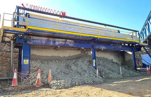
Separation Plant: The material extracted from the tunnels excavation requires a treatment which has two main functions, on one hand to reduce the water and additives consumption needed for the excavation fluid and, on the other hand, to ease the take back and the transport of the material from the excavation. Including such material separation equipment into the tunnels execution is widespread and almost mandatory in most of circumstances. The separation plant consist in a system of several stages in which the fluid from the excavation face, is pumped to be driven, in first place, through a set of cyclones which sort the lower sized particles and, in second place, through several sieves to sift the different grain sizes carried by the fluid. All the dry material is poured into a point with easy access for charging and transport equipment. The separation plant performing is simple but it requires deep previous knowledge of the ground condition in order to adjust the different stages and get an efficient treatment.
-
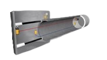
Filter Press: For close shield Tunnel Boring Machines is usual to work in ground which excavation generates great amounts of very small sized solids such as clays and silts. These particles highly increase the fluid density in such way that it must be discarded and replaced with new fluid. Filter press avoid wasting resources in excess so they can sort the smallest particles carried by the fluid, reducing tunnelling process water consumption in the mentioned ground conditions. The filter press process consist in a series of filter cloths through which the fluid circulation is forced. Once reached the necessary pressure inside the filter, the liquid fraction is extracted by suction, leaving a wet cake comprised by the small sized particles, suitable for disposal into the authorized areas of the working place.
Separation plant


Filter press

Guidance Systems
The different guidance systems used in tunnels construction by means of TBMs, are dependent, on one hand, of the lining type used for the tunnel, meaning, it will depend on whether is a pipe jacking or segmental lining tunnel, and, on the other hand, of the tunnel alignment, that is, whether it is a straight or a curved tunnel.
The pipe jacking is a process in which the lining is always kept moving so there are no fixed coordinates points inside the tunnel, therefore a system able to measures these coordinates movement will be necessary whereas in segmental lining tunnels it will always be possible to define points with fixed coordinates because the lining is installed in its final position.
The guidance systems are always comprised by 2 access levels. The first level just show the position and orientation information of the TBM necessary for the pilot to operate the driving equipment of the machine, while in the second level the tunnel alignment definition system is included so the survey manager can introduce the alignment data in order to know the appearing deviations through the execution and also show them on the first level.
Electronic Laser System (ELS): it comprises a laser-guide for the advance, installed inside the launching shaft and pointing to the ELS target located at the back of the TBM. It is applied for straight alignments and up to 250 m long.
Electronic Laser System - Hydrostatic Water Leveling (ELS-HWL): this mode uses the laser-guide for the advance and includes the Electronic Hydrostatic Water leveling which shows the height values measured by means of a reference sensor in the launching shaft and in the TBM. It is applied for straight drives up to 400 m long.
Gyro Navigation System (GNS): The gyrocompass installed in the TBM locates the North direction from the machine axis. The effective position of the TBM is obtained by dead reckoning method. The electronic hydrostatic wáter level shows the height values measured by means of a reference sensor in the launching shaft and in the TBM. This system is applied in curved and long drives.


Cutting Tools
Cutting tools are ancillary excavation elements which are located in the so called Cutting Wheel (CW), their main function is to rip and pull out the ground material in order to achieve the penetration of the machine into it.
The kind of tools, their arrangement on the CW and its configuration, strongly rely on the geological conditions within each project, so it is possible to basically distinguish between Rock, Soil and Mixed CW configurations and tools.
The most common and mainly used cutting tools are:
-
Disc/Roller cutters: These cutting tools are used in rock or hard soil conditions. They are made of different hardness steel, depending on the ground conditions, fixed to the CW by a bearing system allowing them to rotate on their own axis.
-
Rippers: Located all over the CW, by the thrust and roll generated by the CW they slowly rip out the ground and put the material into the chamber in order to take it outside the tunnel. These are commonly used in loose soil conditions, due to their fragility it is recommended to check their wear status if the ground is heterogeneous
-
Buckets: These elements are placed on the most external part of the cutting wheel and their main purpose is to drive the cutted material into the excavation chamber behind the face of the CW and so proceed with the extraction.
The most common and mainly used cutting tools are:


